The purpose of EMC design is to find a way to make the amplitude of various interference signals generated by the electronic equipment designed or produced by itself meet the requirements of others; at the same time, it is also necessary to find a way to make the electronic equipment designed or produced by itself under the interference of other electronic equipment. Still working fine. Therefore, EMC standards are generally mandatory. The electromagnetic field can be shielded with a metal casing, and the power input circuit can be isolated with a transformer, and the transformer must also be shielded by electrostatic induction and magnetic induction. However, due to the heavy metal casing and high cost, the other 50-cycle power transformer is bulky, and it is also troublesome to shield it by electrostatic induction and magnetic induction.
This method is only used in some occasions with particularly high requirements, such as: precision test instruments, which are rarely used for general common electrical equipment. Spraying conductive materials on the inner surface of the plastic casing is also an effective method for electromagnetic shielding. For example, spraying graphite on the inner surface of the plastic casing has a very good effect on UHF electromagnetic shielding, because graphite is both conductive and resistive. , is a good material for absorbing electromagnetic waves, it is not easy to reflect electromagnetic waves, and attenuates electromagnetic waves. If you only compare the shielding effect, the shielding effect of graphite on the electromagnetic field is indeed not as good as that of the metal with good conductivity, but the metal shielding also has shortcomings. oscillation.
Most electrical equipment conducted interference is caused by switching power supply. In order to improve the working efficiency of switching power supply, it is generally hoped that the switching on and off speed of the switch is as high as possible, that is, the steeper the front and rear edges of the square wave, the more Well, this result will make the interference generated by the switching power supply more serious, and it will be more difficult to suppress. Therefore, when designing the switching power supply, do not unconditionally pursue the working efficiency of the switching power supply as high as possible.
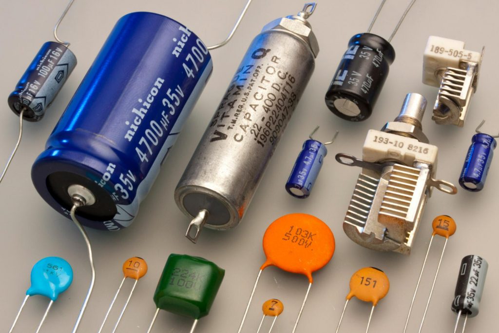
No matter what filter circuit is used to suppress the conducted interference generated by electronic equipment, the main purpose is to minimize the amplitudes of the three interference signals V1, V2, V3 in Figure 6. For example: to suppress the interference signal of V1, the most effective method is to connect a capacitor in parallel at both ends of V1. Because the connection position of this capacitor is special, it needs to meet the safety standards. Therefore, people generally call it Y capacitor; for the same reason, To suppress the V2 interference signal, the most effective method is to connect a Y capacitor in parallel across both ends of V2. Since the Y capacitor will cause the equipment to leak or the passengers will be electrified, it is easy to endanger personal safety, so the two Y capacitors are safety capacitors, their capacity should not be large, and they require high withstand voltage, otherwise, the machine will leak electricity. The safety standard stipulates that the leakage current to the ground of the machine in the subtropical zone cannot exceed 0.7mA, and the leakage current of the machine to the ground in the temperate zone cannot exceed 0.35mA. Therefore, the total capacity of the Y capacitor generally cannot exceed 4700P.
Special reminder, the Y capacitor is a safety capacitor, and it can only be used after passing the witness of the safety inspection department. The withstand voltage of Y capacitors is generally marked with safety certification marks and AC250V or AC275V, but its real DC withstand voltage is as high as 5000V or more. Therefore, Y capacitors cannot be replaced with capacitors such as AC250V or DC400V.
The most effective way to suppress the interference signal of V3 is to connect a capacitor in parallel at both ends of V3. Because the connection position of this capacitor is special, it also needs to meet the safety standards. Therefore, it is generally called X capacitor. The X capacitor is also a safety capacitor, and its capacity can be larger than that of the Y capacitor, but a safety resistor must be connected in parallel at both ends of the X capacitor to prevent the power cord plug from being charged for a long time when the power cord is unplugged and inserted. The safety standard stipulates that when the power cord of the machine at work is unplugged, the voltage (or ground potential) charged at both ends of the power cord plug must be less than 30% of the original voltage within two seconds.
X capacitors are also safety capacitors and must be certified by the safety inspection department before they can be used.
The withstand voltage of X capacitors is generally marked with safety certification marks and AC250V or AC275V, but its real DC withstand voltage is more than 2000V. When using it, do not use AC250V, or DC400V capacitors.
X capacitors generally use polyester film safety capacitors with relatively large ripple current. These capacitors are generally large in size, but the current that allows instantaneous charge and discharge is also large, that is, the internal resistance is relatively small. The ripple current index of ordinary capacitors is generally very small, and the dynamic internal resistance is relatively large. If ordinary capacitors are used instead of X capacitors, except that the withstand voltage conditions cannot be met, the general ripple current index is also difficult to meet the requirements.
In fact, it is impossible to completely filter out conducted interference signals by using Y capacitors and X capacitors alone. Because the spectrum of the interference signal is very wide, it basically covers the frequency range of tens of KHz to hundreds of MHz or even thousands of MHz. The filtering of low-end interference signals requires a large-capacity filter capacitor, but due to the limitation of safety conditions, the capacity of the Y capacitor and the X capacitor cannot be used large; for the filtering of high-end interference signals, the filtering performance of large-capacity capacitors is also Very poor, especially the high-frequency performance of polyester film capacitors is generally poor, because it is produced by winding process, and the high-frequency response characteristics of polyester film dielectrics are far from ceramic or mica. Film dielectrics all have adsorption effect, which will reduce the operating frequency of the capacitor. The operating frequency range of polyester film capacitors is about 1MHz, and its impedance will increase significantly beyond 1MHz.
Therefore, in order to suppress the conducted interference generated by electronic equipment, in addition to selecting Y capacitors and X capacitors for filtering, it is generally necessary to select multiple inductive filters together to filter the interference. Inductive filters are low-pass filters, but inductive filters also have many types and countless specifications, such as: differential mode, common mode, and high frequency, low frequency, etc. Each inductance is mainly for a small frequency. It works by filtering out interfering signals, but has little effect on filtering out interfering signals of other frequencies. Because an inductor with a large inductance has a large number of coil turns and a large distributed capacitance, the high-frequency signal will be bypassed through the distributed capacitance. In addition, the magnetic core with high magnetic permeability has a low operating frequency. At present, most of the operating frequencies of the inductance filter cores widely used in China are below 75MHz. For occasions with high operating frequency requirements, high-frequency toroidal cores must be selected. The magnetic permeability of high-frequency toroidal cores is generally not high. But the leakage inductance is very small.