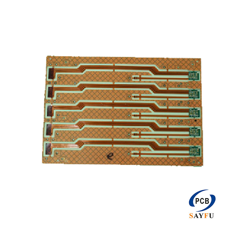
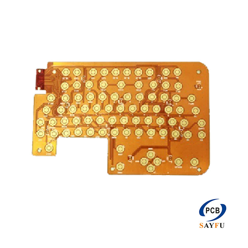
Flexible circuit boards (FPC) are taking center stage in component assembly as smart wearables gain popularity, with space constraints pushing SMD surface mounting on FPC to become a hot trend in SMT. Unlike rigid PCB, FPC’s weak rigidity makes assembly far more difficult, and we’ll clarify these differences below.
FPC vs. PCB: Differences in Welding, SMT Placement & Reflow Soldering
The welding process for flexible circuit boards
- Like the PCB process, through the operation of the stencil and solder paste printer, the solder paste is covered on the FPC and the rigid-flex board. But the surface of FPC is not flat, so we need to use some fixing devices or reinforcement for fixing. We usually paste reinforcement in the component area of the FPC.
SMT component placement
- Under the current trend of miniaturization of SMT components, small components will cause some problems during the reflow soldering process. If the FPC is small, extension and wrinkles will not be a serious problem, so that the SMT frame can be reduced or marking points can be increased. If you don’t want to stick the stiffener to the bottom of the component, you may need flexibility after assembly. Therefore, SMT fixture will be a good choice.
Reflow soldering process of flexible circuit boards
- Before reflow soldering, FPC must be dried. This is an important difference between the FPC and PCB component placement process. In addition to the dimensional instability of flexible materials, they are also relatively hygroscopic. They absorb water like sponges. Once the FPC has absorbed the moisture, the reflow soldering must be stopped. PCB also has the same problem, but has a higher tolerance. FPC needs to be preheated and baked at a temperature of 225°-250°. This preheating and baking must be completed quickly within 1 hour. If it is not baked in time, it needs to be stored in a dry or nitrogen storage room.